National Instruments article on imaginSYS Multi-Channel Spectrometer
Independent 8 channel MR Spectrometer with advanced software and sequence capability (see MR Software and Sequence products for specifications) for clinical and research applications and also for OEM MR System integrators. Additional modules can be added to create 16, 24 or 32 channel systems. A range of Gradient and Radiofrequency Amplifiers can be sourced and integrated into the RF shielded single cabinet spectrometer enclosure.
Transceiver System
- RF System Operating Frequency 250KHz-300MHz
- Frequency Resolution 1 Hz Receiver Digital Quadrature
- Receiver Gain 60 db
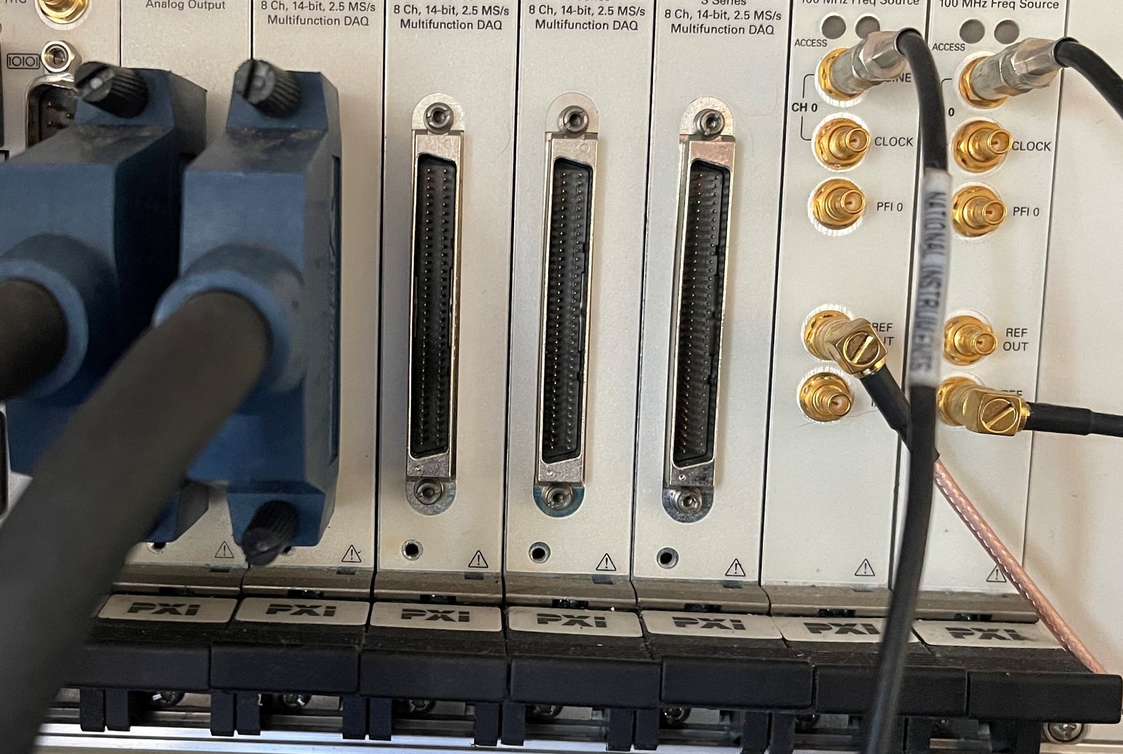
- 8-32 Data Acquisition Channels
- 8 Channels supplied as standard
- Sampling Rate Maximum 2MSPS ,
- Channel Sampling Resolution 14-16 Bits
- Transmitter Digital profile generation
- RF Modulator Output Voltage (max 200mV into 50 Ohms)
- RF Gate Output Voltage (max +/-10V)
- Gradient System Gradient Output (max) +/- 10V for X,Y,Z axes (can be limited to user specification)
- Resolution 16 Bits Maximum Output Rate 1MHz
- Channel Pre-Emphasis Programmable digital filter for each axis
Computer
- Control/Display System - Industry Standard PC
- Display: high resolution digital monitor
- Image format: LabView .lvm Raw Data Format LabView .lvm, DICOM
- Image reconstruction/store < 0.2 seconds per image, 2DFT, 256 x 256 matrix
- Network Ethernet 100 MBits/Sec: Note – we recommend system is not connected to a network
- Hard Copy Standard PC Printers
Software
- Operating System : Windows
- Menus, Dialog Boxes, Scroll Bars
- Study Register
- Select Sequence
- Scan - Set up scan parameters
- Calibrate - Manual using Tune Sequence
- Process - 2DFT/3DFT Reconstruction module
- Display - Window and Level Greyscale images
- System parameter edit
- User defined sequence edit through Waveform Editor (option)
- Help - Pdf file with user instructions
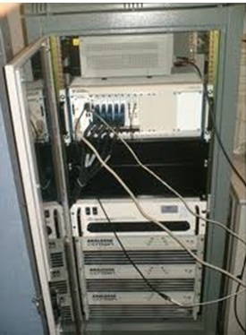
System Dimensions
- System Interface Enclosure 26U 19” Rack Total Weight 100Kg
- Power Requirements Inlet Single phase filtered mains Voltage 240 V AC 50 Hz Power Consumption < 3kVA
- Power Conditioner Optional (Imaging Systems Design Ltd reserve right to specify)
- Earth Bonding To appropriate UK National Standards (PAT testing required on site)
- Environmental Requirements - Temperature Temperature controlled room ( +/- 1C over enclosure)
- No direct sunlight on system enclosure/monitors)
- Humidity <70% non-condensing
- The spectrometer can be located in the technologists scan room or the techniques room.
- An umbilibal cable and filter panel are used with a standard waveguide.
- An Independent Research Coil Insert System is located within the magnet bore.